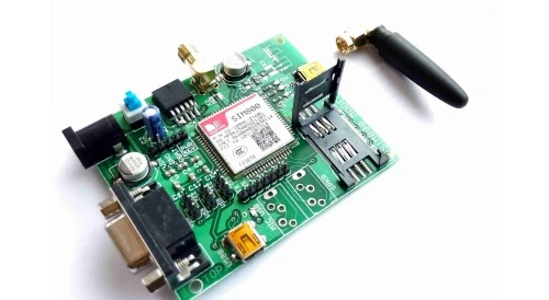
SIM800 module is a GSM quad band module. It is based on the latest GSM/GPS module SIM808 from SIMCOM, supports GSM/GPRS Quad-Band network and combines GPS technology for satellite navigation.It has high GPS receive sensitivity with 22 tracking and 66 acquisition receiver channels. Besides, it also supports A-GPS that available for indoor localization. The module is controlled by AT command via UART and supports 3.3V and 5V logical level.
Features[]
- Quad-band 850/900/1800/1900MHz
- GPRS multi-slot class 12/10
- GPRS mobile station class B
- Compliant to GSM phase 2/2+
- Class 4 (2 W @ 850/900MHz)
- Class 1 (1 W @ 1800/1900MHz)
- Bluetooth: compliant with 3.0+EDR(Needs firmware updation - Contact SIMCOM)
- Control via AT commands
- Supply voltage range 5V ~ 12V
- Low power consumption
- Operation temperature:-40? ~85?
- Standard SIM Card
Powering the module[]
Firstly insert the SIM card in the sim holder. Make sure to use a normal SIM card (Micro or nano SIM cards are not supported)
- Connect the GSM modem to the PC using a Mini USB cable connect to the computer.
- Connect a 5-12V/9V 1A adapter to the power jack provided on the GSM modem. The voltage regulator regulates the voltage to 4.1V.
- Switch on the module using the ON/OFF switch provided, note when you switch on, the power LED will glow. It shows that the modem has got the power required for its operation.
- When you connect the power, Network LED will glow for approximately 1sec. After that, it will blink with a delay of approximately half sec. That means the SIM card is searching for network. If the SIM card has connected to a network, then the Network LED will blink with a delay of approximately 4sec. Depending on the network strength, the time to connect to a network may vary. If there is no SIM card in the modem, the Network LED blinks with a delay approximately half sec.
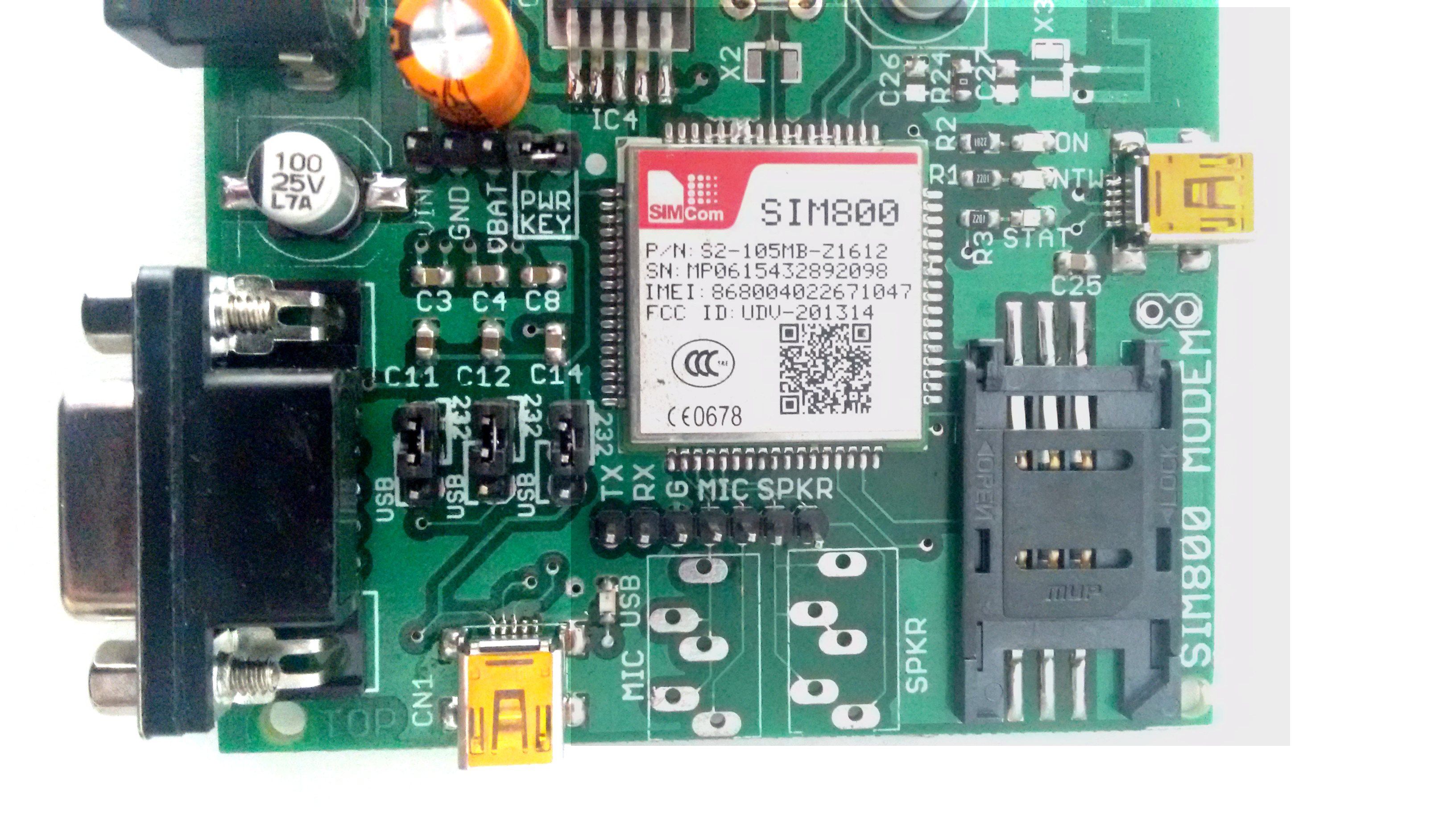
Jumper configurations[]
Enable module Power ON[]
connecting to RS232 port[]
connecting to USB port[]
Connecting to TTL pins =[]
Testing in Windows[]
To communicate with the network we use ELEMENTZ GSM Modem Test Utility software. It is an executable file which supports serial data transmission and reception similar to HyperTerminal.
Using the test utility[]
- The steps required for connecting the modem to the PC is shown below:
- Right click My Computer ? select the Device manager ? Ports(COM & LPT).

- Note the COM PORT. Here you can see it's COM3.
- Double click GSM Tester.exe ? click on Scan ports. The Status box will show “Port Scan complete”.

- Click on Port drop-down menu. Select COM Port for your device. Here it's COM3.

- Then click on Open port. The status box will show Port opened successfully. Message cleared. Connect the 12V 1A adapter to the power jack of the modem. You can see the following details in the status box.
“+CFUN: 1 ”

“+CPIN: READY”

“CALL READY”  This means that the modem is ready for normal functioning.

Please note if SIM is not inserted then it will show “+CPIN: NOT INSERTED”.
Making a CALL[]
To make a call, enter the phone number and press the Call button.
The status box will show Data received: ATD903720XXXX; . This is the AT command for making a call.
If a call is coming to the GSM modem, a series of “RING” will appear on ths Status box. If you want to connect to the call ,then type “ATA” in the AT command window and press “Execute“.

Sending message[]
The first thing you have to do before sending a message is to make the modem to text mode. To do that type AT+CMGF=1;&W in the AT command window and press execute. DO NOT TYPE THE DOUBLE QUOTES. &W is used to write to the SIM900a memory permanently.
To send a message, type the phone number in Phone number window and the message content in the Message window and press the Send button.
You can see that after the message has been sent, the modem gives a response”+CMGS: 234?. From this you can confirm that message has been sent successfully.

The number 234 means 234 messages has been sent from the modem.
The AT command for sending message is AT+CMGS=”903680XXXX?. When you press enter , > prompt will appear. Type the content of the message and after that press Ctrl+z to send the message.
Using Putty[]
PuTTY is a serial emulator which is works with windows OS.
Double click putty.exe ? select serial bullet?change the com port number to the number shown earlier in the device manager ?click open.
Then a new window is opened and we give the commands in the window to communicate with the GSM modem and the other network through GSM modem. The commands are called ‘AT commands’ or ‘Attention commands’. To check the connection type AT in the putty command window and press enter. If there is a connection it displays OK.

Please note if SIM is not inserted then it will show “+CPIN: NOT INSERTED”.
Make call[]
To make a call type ATD<phone number>; e.g.: ATD9020XXXXXX;
If a call is coming to the GSM modem, a series of “RING” will appear on the window. If you want to connect to the call ,then type “ATA” & press enter.
Send message[]
To send a message, first you may have to change the message format from PDU to TEXT by typing AT+CMGF=1;&W . To send the message type the following AT+CMGS=’’9020XXXXXX” and press ENTER After this, you can see the message prompt (>). Then type the message and press Ctrl+z to send the message.
Or press Esc to abort.

You can see that after the message has been sent, the modem gives a response”+CMGS: xx?. From this you can confirm that message has been sent successfully.
eg: “+CMGS: 23”
The number 23 means 23 messages has been sent from the modem.
Testing in Linux PC[]
The test utility is developed using Python with PySerial and PyQT modules. The code is tested in Ubuntu 12.04 and LinuxMint 17.

Program Features:
- Auto scan Serial/COM ports in Linux when clicked on the device COMBO button
- Configurable Baud Rate
- Call button needs only Phone number in the TextBox above it.(Command compatible with SIM900 Modules)
- AT command input support
- Intelligent button enabling functionality.
- Serial Data logger
- Invalid ASCII Data notification– Indicate wrong BaudRate selection
The source code is available through our GITHUB channel GSM Tester.
For users not familiar with Python and configuring python module, a standalone executable with all dependencies is also distributed along with the source code.
For executing the python code use the following command from the Terminal.
tar -xvf GSM_tester_Linux.tar.gz
cd Linux
python GSM_ui.py
Note: Users require PyQt and PySerial in the system. The standalone executable is built using pyinstaller utility.
For running the standalone executable use the following commands
cd dist/GSM_ui
chmod 777 +x GSM_ui
./GSM_ui
Connecting with RaspberryPi[]
Connect a USB to Serial converter to the RaspberryPi USB port. A compatible USB to Serial converter can be obtained from this link.
Create a new file named serial_test.py by typing the following command
nano serial_test.py
write the following lines to the file
"""
author: dhanish
company: Elementz Engineers Guild Pvt Ltd
Created on: Tue Aug 12 20:17:12 2014"""

import serial
import time
ser = serial.Serial(‘/dev/ttyUSB0’,9600,timeout=1) # 9600 is the default Baudrate for SIM800 modem
ser.flush()
ser.write(‘ATD9020XXXXXX;\r’) # AT command to call a number using GSM Modem — Edit here
#ser.read(2) # read 2 bytes of data from the serial port
time.sleep(10) # wait for 10 secondsser.write(‘ATH\r’) # Hold the call
ser.close() # close the serial port
And finally save the file using Ctrl+O and Ctrl+X Run the following command in the terminal
python serial_test.py
Connecting with Arduino[]
The code is tested with SIM900A and Arduino UNO. Connect the Tx and Rx pins of arduino pins to Rx and Tx pins of GSM Modem.
Using Hardware serial[]

Note: The UART(Serial) pins should be cross connected, ie. GSM Tx –> Arduino Rx and GSM Rx –> Arduino Tx. Make the ground common between Arduino and GSM modem.
TTL pins can be seen just behind the 9 pin DB9 connector. If you are using DB9 connector for interfacing you need MAX232 circuitry for converting RS232 output of DB9 to TTL levels.
Copy and paste the following code to your Arduino IDE as a starting point for GSM-Arduino interfacing test.
- Note: Before powering SIM800 module user should insert the SIM into the module.
Change the phone number in the below code before running the code.
/*
Author: Dhanish
Created on: 19-08-2014
Company: Elementz Engineers Guild Pvt Ltd
Run this code only after SIM800 Module has powered and connected to a Network.
Please make a call to the module knowing whether the connection is established.
If connected a ring will be heard at the caller end
*/

void setup() {
   // initialize serial communications at 9600 bps:
   Serial.begin(9600);

   delay(10000);
   // print the serial data to GSM
   Serial.print("ATD9020XXXXXX;" ); // change here to call a number using SIM800
   // wait 10 seconds before the next loop
   delay(10000);
   Serial.print("ATH" ); // hold the call
}

void loop() {
}
Using Software serial[]
Another code using Software serial is as seen below
Note: Connect as follows
digital pin 10 — connect to TX of GSM Modem digital pin 11 — connect to RX of GSM Modem
/*
Author: Dhanish Vijayan
The circuit:
* RX is digital pin 10 (connect to TX of GSM Modem)
* TX is digital pin 11 (connect to RX of GSM Modem)
*/
#include <SoftwareSerial.h>

SoftwareSerial mySerial(10, 11); // RX, TX

void setup()
{
   // Open serial communications and wait for port to open:
   Serial.begin(9600);

   Serial.println("Calling through GSM Modem");

   // set the data rate for the SoftwareSerial port
   mySerial.begin(9600);
   delay(2000);
   mySerial.println("ATD81290255XX;"); // ATD81290255XX; -- watch out here for semicolon at the end!!

   Serial.println("Called ATD81290255XX");
}

void loop() // run over and over
{
   // print response over serial port
   if (mySerial.available())
      Serial.write(mySerial.read());
}
Arduino sample code can be downloaded from our GitHub channel.